Measuring templates bloat

Recently I’ve been investigating slow compilation of source files which used one particular library. The library was written in-house and has its roots in pre-C++11 era, including abundant usage of Boost. The library itself provides a sophisticated mechanism of reflection and operates with type-erased objects. Obviously, it heavily relies on the C++ type system and has a lot of template code.
Boost became my primary suspect almost immediately – it’s notorious for compiler torture and I personally try to avoid it wherever possible. So the most prominent red flags like Boost.MPL were almost completely removed and other pieces were converted to their C++11 standardised counterparts. Results, however, weren’t inspiring – compilation time moved a bit, but only marginally. The bottleneck was somewhere else.

Looking at MSVC’s time report (“/d2cgsummary”) didn’t provide anything meaningful –  it basically stated that each file contained dozens of functions with “Anomalistic Compile Times”™️. No details why though.
GCC’s time report (“-ftime-report”), on the other hand, was much more helpful. It clearly showed that the lion’s share of time was spent on “phase opt and generate”, which, to my understanding, is actual instructions generation. That was somewhat surprising given the fact that the majority of these source files weren’t large nor performed any rocket surgery.

It should be mentioned that almost all reflection code in that library was written in templates, which makes sense. And, apparently, the compiler was spending time generating instructions for these methods per each instantiation type over and over again for each translation unit, to be later simply thrown away by the linker. It’s hard to estimate the number of instantiation types in the final product itself, but 50-100 can serve as ballpark estimation. So I decided to make an experiment and tried offloading some portions of templated code into a private non-templated “base” class. It immediately became evident that removing even tiny pieces of code, like the formatting of an exception message, results in a reduction of overall object files size (*.obj) by literally megabytes.

In this post I, roughly model the situation with synthetic code generation. Imagine the following pattern (let’s call it Pattern 1):

struct Base {
    virtual ~Base() = default;
    virtual void Method(int v) = 0;
};

template <typename T>
struct Impl : Base {
    void Method( int v ) override {
        if( v == 0 ) // some error checking
            throw std::logic_error
            ( "you're so unlucky with Method() for \'"s + typeid(T).name() + "\'!" );
        // some useful stuff
    }
};

struct Type{};

Base *Spawn_Type() { return new Impl<Type>; }

It’s quite easy to generate such code for a given number of class methods and instantiation types. Each additional method adds an entry in a virtual methods table and a templated implementation in Impl<T> by analogy with Method(). Each additional instantiation type introduces a new type and a new spawning function by analogy with Type / Spawn_Type().
And, for comparison, below is a slightly altered version (Pattern 2). ImplBase provides non-templated functionality and Impl<T> does just the same but redirects the exception composing and throwing to the ImplBase class. Performance hit introduced by additional function call can be neglected in 99.9% of cases.

// [...]
struct ImplBase {
    static void ThrowLogicErrorAtMethod( const std::type_info& typeid_t );
};

template <typename T>
struct Impl : Base, private ImplBase {
    void Method( int v ) override {
        if( v == 0 ) // some error checking
            ThrowLogicErrorAtMethod( typeid(T) );
        // some useful stuff
    }
};
// [...]

This repo contains generators and measurement scripts for both patterns. Scripts execute these generators for each of combinations of [1..20] methods by [1..20] instantiations and measure compilation of produced source code. The measurements shown below were made with “Apple LLVM version 10.0.0 (clang-1000.11.45.5)” on i7-3520M with “-std=c++17 -O2 -c” flags.

These are the compilation times and the object file sizes for the first pattern. Both compilation time and file size scale roughly proportionally to both number of methods and types. In the worst case scenario (20 methods x 20 types) it takes almost 3 seconds to compile the code which does basically nothing apart from error reporting. If there would be any actual code instead of “// some useful stuff” the graph will look much scarier.

The graphs below show the scaling of the second pattern. The worst-case scenario takes 0.75s to compile instead of 2.73s with the first pattern. The object file is 4 times smaller in that case.

Of course, both patterns generated a completely synthetic code which is far too simple to look at concrete absolute numbers. Adding any reasonable logic into these methods would radically shift the results. But I guess it’s safe to assume that delta between these two patterns will not go anywhere – a compiler will still have to generate these instructions regardless of other complexity. So it should be fair to look at delta numbers:

These delta numbers show something interesting. For instance, for the case of 10 methods and 10 instantiation types (which doesn’t seem too extreme), the difference is about half a second of compilation time per file. Or, to rephrase, there is a choice of two approaches:
a) Pattern I: clearer code – easier to maintain, but it costs 0.4 seconds of wait time per compilation per file;
b) Pattern II: a bit more obfuscated code – harder to maintain, but doesn’t introduce additional cost in terms of compilation time.
This choice, as usual in engineering, doesn’t provide a “right” option – it’s always a tradeoff. Often times, however, such choices are being done unconsciously just because something is considered to be a “default” way by the C++ community.

The “zero-cost abstractions” are sometimes being presented as the main C++ feature, but there are many hidden costs – graphs above show just one aspect of such penalties. The recent debate on Modern C++ vs. GameDev touched this problem and the ascetic approach of “C with classes” definitely has many valid points. At least such code compiles fast.

IO2D demo: Maps

Introduction
This blog post describes another IO2D demo I wrote as a showcase of the library’s capabilities. The demo is a simple yet working GIS renderer. The OpenStreetMap service is used as a raw data provider, allowing for the visualization of any reasonably sized rectangular region. The demo supports querying OSM servers directly or loading existing data files. The entire source code of the sample is less than 800 lines of code, of which 250 lines deal with the rendering itself and another 360 lines handle the data model.

OpenStreetMap API
OpenStreetMap has an API which lets you download map data specified by an arbitrary coordinate bounding box. This interface has a number of limitations related to data transfer. For instance, the API might not fetch more than 50K nodes in some cases. Also, the interface may provide an incomplete geometry, which happens when a complex region is only partially covered by the bounding box. The latter is especially apparent with water regions like rivers, lakes and coasts. These limitations are however quite tolerable for sample code.
The API is accessible via the following HTTP GET request: /api/0.6/map?bbox=MinLong,MinLatt,MaxLong,MaxLatt. For example, these are coordinates for Rapperswil:

wget https://api.openstreetmap.org/api/0.6/map?bbox=8.81598,47.22277,8.83,47.23

The returned data will contain a raw OpenStreetMap XML file with nodes, ways and relations between them.

External libraries
Obviously (no sarcasm implied), C++ has no standard networking capabilities, so some external facility is required to download map data. Boost.Beast was chosen to talk with OSM servers in the sample code. Once a file is received, that XML has to be parsed. PugiXML was employed to deal with it.

Data representation
This demo uses a very simple interpretation of OpenStreetMap data. Instead of trying to handle myriads of different tags, it grabs objects of several types and ignores everything else. The Model class transforms the input XML file into a set of linear containers which hold all information required to render the map. The OSM format uses 64-bit integers to uniquely identify entities and to maintain connections, which assumes storing objects in some kind of a hash map. The Model class transforms these unordered identifiers into raw array indices to reduce the impact on the memory subsystem and to enforce consistency.
The transformed map data is accessible via several POD types. A Node object represents some point of interest and carries just a pair of coordinates. A Way object represents a collection of Nodes. A Road and a Railway point at some Way to describe an underlying geometry. A Road also has its enumeration type, like Motorway or Footway, to visually distinguish between different types of roads. A Multipolygon represents a set of outer and inner polygons, which basically means two sets of Way objects. Building, Leisure, Landuse and Water are different types of Multipolygon objects. Landuse also has type information, like Commercial, Construction, Industrial etc. The overall logic model looks like this:

Coordinates transformations
OpenStreetMap works with latitudes and longitudes, so these coordinates must be projected into the convenient Cartesian coordinate system. A simple Pseudo-Mercator metric projection is used to transform input coordinates:

auto pi = 3.14159265358979323846264338327950288;
auto deg_to_rad = 2. * pi / 360.;
auto earth_radius = 6378137.;
auto lat2ym = [&](double lat) { return log(tan(lat * deg_to_rad / 2 + pi/4)) / 2 * earth_radius; };
auto lon2xm = [&](double lon) { return lon * deg_to_rad / 2 * earth_radius; };

It is also worth noting that a precision of 32-bit float values is not enough, so 64-bit double values are used for initial storage and projection. Once Cartesian coordinates are calculated, they are translated and scaled into the range of [0..1].

Polygons composition
OSM lets polygons to be defined as a composition of multiple non-closed Ways. The idea behind this is a sharing of Ways data between several adjacent areas to remove the necessity to declare the same border twice. Such an approach leads to an intermediate step of composing polygons out of pieces. To complicate matters, OSM does not mandate a strict order of Ways declaration and only requires that a closed polygon should be composable out of a given set. This even includes a possible interpretation of Way’s nodes in the reversed order: ABC + EDC + AFE = ABCDEF. The goal of this step is to get a set of closed Ways, so this data can be fed to a graphics API later. The sample code implements the polygons composition in a pretty blunt brute-force manner. This implementation works well enough on real data, but in theory, its performance may significantly degrade due to the high algorithmic complexity.

Rendering
Once the data is parsed and transformed, the Render class can start drawing the map. The drawing process is sequential and follows this order: landuse regions, leisure regions, water regions, railways, highways and buildings.
Each object has to be represented as a path before it can be drawn. Two methods do that: PathFromWay and PathFromMP. The difference between them is that PathFromWay deals with non-closed ways while PathFromMP composes a path from a collection of closed Ways. Straight lines are used to connect nodes along a Way:

io2d::interpreted_path Render::PathFromWay(const Model::Way &way) const { 
  if( way.nodes.empty() )
    return {};

  const auto nodes = m_Model.Nodes().data(); 

  auto pb = io2d::path_builder{};
  pb.matrix(m_Matrix);
  pb.new_figure( ToPoint2D(nodes[way.nodes.front()]) );
  for( auto it = ++way.nodes.begin(); it != std::end(way.nodes); ++it )
    pb.line( ToPoint2D(nodes[*it]) ); 
  return io2d::interpreted_path{pb};
}

Each region type has its visual properties like fill color, outline color, stroke width and dashes pattern. These properties are defined once during construction of a Render object and most of the times are used as-is. The exception is road/railroad width, which is defined in meters and has to be scaled into pixel width according to a map scale and a window size.
This render code utilizes only solid color brushes, however nothing stops us from using image brushes instead. The main issue with them is that such images need to be drawn by someone and IMHO the programmer art should be avoided like the plague.
Some regions might have holes inside, which is specified via separation of outer and inner polygons. The demo combines such polygons into a single path which is drawn under io2d::fill_rule::winding rule.
The drawing itself is pretty straightforward, for example, these 7 lines of code display the buildings on the map:

void Render::DrawBuildings(io2d::output_surface &surface) const {
  for( auto &building: m_Model.Buildings() ) {
    auto path = PathFromMP(building);
    surface.fill(m_BuildingFillBrush, path);
    surface.stroke(m_BuildingOutlineBrush, path, std::nullopt, m_BuildingOutlineStrokeProps);
  }
}

Examples

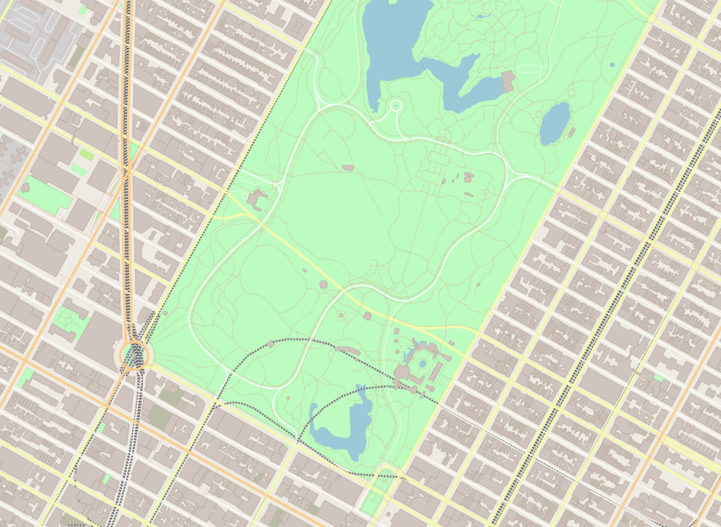
Central Park:
./maps -b -73.9866,40.7635,-73.9613,40.7775

Acropolis of Athens:
./maps -b 23.7125,37.9647,23.7332,37.9765

Vatican:
./maps -b 12.44609,41.897,12.46575,41.907

Performance statistics
This demo renders the entire graphics set from scratch every frame. This, of course, is not how such software usually behaves, but for the sake of simplicity, the choice was not to introduce any caching. So how does the Reference Implementation cope with this task? For testing purposes, I used the Core Graphics backend running on macOS 10.13. The source code was compiled in Xcode9.3 in Release configuration. The hardware underneath is an old 2012 MacMini with a 2,3GHz Core i7 processor. The maps were rendered at the resolution of 1920 x 1080.

Dataset Central Park Acropolis of Athens Vatican
Nodes 36,909 51,126 27,614
Ways 4,636 6,105 3,410
Roads 1,082 989 1,060
Railroads 41 42 44
Buildings 2,329 4,336 889
Leisures 44 77 101
Waters 13 0 31
Landuses 23 66 66
FPS 11 9 14

Conclusion
So, it takes 90ms to display the Central Park dataset, which consists of ~37K points in ~3,5K paths. Not a terrible result for a software rendering engine, which shows that the library is clearly capable of handling a casual graphics output. Of course, a hardware-accelerated backend like Direct2D would perform much faster, but it’s not here yet.

The sample’s source code is available here: https://github.com/mikebmcl/P0267_RefImpl/tree/master/P0267_RefImpl/Samples/Maps.

IO2D demo: CPULoad

Introduction
It’s no secret that standard C++ is stuck in the ‘70s in terms of human-machine interaction. There is a console input-output with a handful of control characters and that’s basically it. You can use tabulation, a carriage return and, if you’re lucky, a bell signal. Such “advanced” interaction techniques of VT100 like text blinking, underscoring or coloring are out of reach. Of course, it’s possible to directly access some platform-specific API, but they differ quite a lot across platforms and are usually rather hostile to C++ idioms. InterfaceKit of BeOS was AFAIK the only native C++ graphics API. Some 3rd party library and/or middleware could serve as an abstraction layer, but this automatically brings a bunch of problems with building and integration, especially for cross-platform software. So, displaying a simple chart or a cat photo becomes an interesting quest instead of a routine action.

At this moment there’s a proposal to add standardized 2D graphics support to C++, known as P0267 or simply IO2D. It hasn’t been published as TS yet and there’s some controversy around it, but still, the proposal was proven to be implementable on different platforms and the reference implementation is available for test usage. The paper introduces concepts of entities like surfaces, colors, paths, brushes and defines a set of drawing operations. A combination of available drawing primitives with a set of drawing properties already allows building a quite sophisticated visualization model. Capabilities of the drawing operations generally resemble Microsoft’s GDI+/System.Drawing or Apple’s Quartz/CoreGraphics. The major difference is that IO2D employs a stateless drawing model instead of sequential state setup and execution.

The implementation of the proposed graphics library consists of two major components: a public library interface and a platform-specific backend (or multiple backends). The public interface provides a stable set of user-facing classes like “image_surface”, “brush” or “path_builder” and does not contain any details about the actual rendering process. Instead, it delegates all requests down to the specified graphics backend. The backend has to provide the actual geometry processing, rendering and interaction with a windowing system. To do that, ideally, the backend should talk directly to an underlying operating system and its graphics interfaces. Or, as a “fallback solution”, it can translate requests to some cross-platform library or middleware.

The CPULoad demo
There are several sample projects available in the RefImpl repository, their purpose is to demonstrate capabilities of the library and to show various usage techniques. The rest of this post contains a step-by-step walkthrough of the CPULoad example. This demo shows graphs of CPU usage on a per-core basis, which looks like this:

The sample code fetches the CPU usage information every 100ms and redraws these “Y=Usage(X)” graphs upon a frame update. The DataSource class provides a functionality to fetch new data and access existing entries via this interface:

class DataSource {
public: 
  void Fetch();
  int CoresCount() const noexcept;
  int SamplesCount() const noexcept;
  float At(int core, int sample) const noexcept;
  […]
};

The profiler routine is the only platform-specific part, everything else is cross-platform and runs identically on Windows, Mac and Linux.

The data presentation consists of several parts:
– Window creation and redraw cycle;
– Clearing the window background;
– Drawing the vertical grid lines;
– Drawing the horizontal grid lines;
– Filling the graphs with gradients;
– Outlining the graph contours.

Window creation and redraw cycle
This sample uses a so-called “managed output surface”, which means that the caller doesn’t need to worry about the window management and can simply delegate these tasks to IO2D. Only 3 steps are required to have a windowed output:
– Create an output_surface object with properties like desired size, pixel format, scaling and redrawing scheme.
– Provide a callback which does the visualization. In this case, the callback tells the DataSource object to fetch new data and then it calls the drawing procedures one by one.
– Start the message cycle by calling begin_show().

void CPUMeter::Run() {
  auto display = output_surface{400, 400, format::argb32, scaling::letterbox, refresh_style::fixed, 30};
  display.draw_callback([&](output_surface& surface){
    Update();
    Display(surface);
  });
  display.begin_show(); 
}

Clearing the window background
Paint() operation fills the surface using a custom brush. There are 4 kinds of brushes – a solid color brush, a surface (i.e. texture) brush and two gradient brushes: linear and radial. The solid color brush is made by simply providing a color to the constructor:

brush m_BackgroundFill{rgba_color::alice_blue};

Thus, filling a background requires only a single method call, as shown below. Paint() has other parameters like brush properties, render properties and clipping properties. They all have default values, so these parameters can be omitted in many cases.

void CPUMeter::DrawBackground(output_surface& surface) const {
  surface.paint(m_BackgroundFill);
}

The outcome is a blank window filled with the Alice Blue color (240, 248, 255):

Drawing the vertical grid lines
Drawing lines is a bit more complex operation. First of all, there has to be a path which describes a geometry to draw. Paths are defined by a sequence of commands given to an instance of the path_builder class. A line can be defined by two commands: define a new figure (.new_figure()) and make a line (.line()).
Since it might be costly to transform a path into a specific format of an underlying graphics API, it’s possible to create an interpreted_path object only once and then to use this “baked” representation on every subsequent drawing. In the snippet below, the vertical line is defined only once. Transformation matrices are then used to draw the line at different positions.
Two methods can draw arbitrary paths: stroke() and fill(). The first one draws a line along the path, while the latter fills the interior of a figure defined by the path. Drawing of the grid is performed via the Stroke() method. In addition to brushes, this method also supports specific parameters like “stroke_props” and “dashes”, which define properties of a drawn line. In the following snippet, those parameters set a width of 1 pixel and a dotted pattern.

stroke_props m_GridStrokeProps{1.f};
brush m_VerticalLinesBrush{rgba_color::cornflower_blue};
dashes m_VerticalLinesDashes{0.f, {1.f, 3.f}};

void CPUMeter::DrawVerticalGridLines(output_surface& surface) const {
  auto pb = path_builder{}; 
  pb.new_figure({0.f, 0.f});
  pb.line({0.f, float(surface.dimensions().y())});
  auto ip = interpreted_path{pb};
 
  for( auto x = surface.dimensions().x() - 1; x >= 0; x -= 10 ) {
    auto rp = render_props{};
    rp.surface_matrix(matrix_2d::init_translate({x + 0.5f, 0}));
    surface.stroke(m_VerticalLinesBrush, ip, nullopt, m_GridStrokeProps, m_VerticalLinesDashes, rp);
  }
}

The result of this stage looks like this:

Drawing the horizontal grid lines
The process of drawing the horizontal lines is very similar to the previous description with the only exception. Since horizontal lines are solid, there’s no dash pattern – nullopt is passed instead.

brush m_HorizontalLinesBrush{rgba_color::blue};

void CPUMeter::DrawHorizontalGridLines(output_surface& surface) const {
  auto cpus = m_Source.CoresCount();
  auto dimensions = surface.dimensions();
  auto height_per_cpu = float(dimensions.y()) / cpus;
 
  auto pb = path_builder{};
  pb.new_figure({0.f, 0.f});
  pb.line({float(dimensions.x()), 0.f});
  auto ip = interpreted_path{pb};
 
  for( auto cpu = 0; cpu < cpus; ++cpu ) {
    auto rp = render_props{};
    rp.surface_matrix(matrix_2d::init_translate({0.f, floorf((cpu+1)*height_per_cpu) + 0.5f}));
    surface.stroke(m_HorizontalLinesBrush, ip, nullopt, m_GridStrokeProps, nullopt, rp);
  }
}

A fully drawn grid looks like this:

Filling the graphs with gradients
Filling the graph’s interior requires another kind of brush – the linear gradient brush. This kind of brush smoothly interpolates colors along some line. The linear brush is defined by two parameters: a line to interpolate along and a set of colors to interpolate. The gradient in the snippet consists of three colors: green, yellow and red, which represents different levels of usage: low, medium and high. The artificially degenerate line of {0, 0}-{0, 1} is used upon the construction of the gradient, this allows to easily translate and scale the gradient later.
Each data point is used as a Y-coordinate in a path, which is being built from right to left until either the left border is reached or no data remains. Both the path and the gradient are then translated and scaled with the same transformation matrix. In the first case, the coordinates of the paths are transformed, while in the second case the anchor points of the gradient are transformed.

brush m_FillBrush{ {0, 0}, {0, 1}, { {0.f, rgba_color::green}, {0.4f, rgba_color::yellow}, {1.0f, rgba_color::red}}};

void CPUMeter::DrawGraphs(output_surface& surface) const {
  auto cpus = m_Source.CoresCount(); 
  auto dimensions = surface.dimensions();
  auto height_per_cpu = float(dimensions.y()) / cpus;
 
  for( auto cpu = 0; cpu < cpus; ++cpu ) {
    auto m = matrix_2d{1, 0, 0, -height_per_cpu, 0, (cpu+1) * height_per_cpu};
 
    auto graph = path_builder{};
    graph.matrix(m);
    auto x = float(dimensions.x()); 
    graph.new_figure({x, 0.f}); 
    for( auto i = m_Source.SamplesCount() - 1; i >= 0 && x >= 0; --i, --x )
      graph.line({x, m_Source.At(cpu, i) }); 
    graph.line({x, 0.f});
    graph.line({float(dimensions.x()), 0.f});
    graph.close_figure();
 
    auto bp = brush_props{};
    bp.brush_matrix(m.inverse());
    surface.fill(m_FillBrush, graph, bp);
  }
}

Filled graphs then look like this afterwards:

Outlining the graph contours
The graph looks unfinished without its contour, so the final touch is to stroke the outline. There is no need to build the same path twice, as the previous one works just fine. The only difference is that the contour should not be closed, so the path is simply copied before the two last commands. A brush with transparency is used to give the outline some smoothness.

brush m_CountourBrush{ rgba_color{0, 0, 255, 128} };
stroke_props m_ContourStrokeProps{1.f};
[…]
    graph.line({x, 0.f});
    auto contour = graph; 
    graph.line({float(dimensions.x()), 0.f});
    […] 
    surface.stroke(m_CountourBrush, contour, nullopt, m_ContourStrokeProps);
  } 
}

And this last touch gives us the final look of the CPU activity monitor:

Conclusion
In my humble opinion, the 2D graphics proposal might bring C++ a solid foundation for visualization support. It’s powerful enough to build complex structures on top of it – here I can refer to the sample SVG renderer as an example. At the same time, it’s not built around some particular low-level graphics API (i.e OpenGL/DirectX/Mantle/Metal/Vulkan), which come and go over time (who remembers Glide?). What is also very important about the proposal is its implementability – I wrote the CoreGraphics backend in ~3 months on a part-time basis. It can be assumed that writing a theoretical Direct2D backend might take about the same time. While it’s easy to propose “just” a support for PostScript, SVG or even HMTL5, the practical implementability of such extensive standards is very doubtful. Having said that, I do think that the proposal, while being a valid direction, is far from being perfect and needs a lot of polishing.

Here’s the link to the IO2D implementation:
https://github.com/mikebmcl/P0267_RefImpl
Sample code:
https://github.com/mikebmcl/P0267_RefImpl/tree/master/P0267_RefImpl/Samples
Samples screenshots :
https://github.com/mikebmcl/P0267_RefImpl/tree/master/P0267_RefImpl/Samples/Screenshots

Cryptocurrency mining on iOS devices


XMR-STAK-CPU running on iPad

Disclaimer

This post should not be treated as an advice to use iOS devices as a cryptocurrency mining machine. That can destroy the battery, fry the CPU/SoC, ruin the system’s responsiveness etc. This is a purely academic research driven by sheer curiosity.

Reasons

Since I got my hands on the latest iPad, I was eager to write something to check horsepower of that machine. Thanks to the recent bubble of cryptocurrencies prices, this ridiculous idea appeared. Of course, there’s no sense in trying to mine bitcoins or similar currencies since CPUs can’t compete with specialized solutions like ASICs in mining those. On the other hand, cryptocurrencies based on CryptoNote, like Monero(XMR ticker), have memory-bound properties which make them hard to crack on tiny dumb devices. That brings at least some amount of sense into solving these crypto puzzles on CPUs. I chose the XMR-STAK-CPU mining software, which is available in a source code, to try to run on iOS, first in a simulator and the on a real device.
As part of this porting experiment, I aimed to keep the original source code untouched and to use the files right out of the repository. Oddly enough, the endeavor was successful and within a few days, I got a complete solution. Challenges of porting and the outcome are described below.

Challenges

SSE vs. NEON
The source code of xmr-stak-cpu contains tons of SIMD instructions. Fortunately, there’re no inline assembler instructions and all calls are made through _mm_XXX intrinsics. That means it’s possible to mimic these calls with C-style functions and macros. The same applies to the data type definitions.
Thanks to the SSE2NEON project, the lion’s share of the work is already done and I basically needed only to properly fiddle with the source code. A trick with a precompiled header was used to do it: when the source was built for a real iOS device – SSE2 was mimicked with NEON and the original includes (<x86intrin.h>, <intrin.h>, <immintrin.h>) were suppressed by defining theirs include guards in advance. Nothing was substituted for iOS Simulator builds since it runs on an x86 machine and there’re no NEON instructions there.

But of course, that could not be absolutely smooth. A couple of x86 instructions was missing in SSE2NEON: _mm_prefetch, _mm_set_epi64x, _mm_cvtsi128_si64, _mm_aesenc_si128 and _mm_aeskeygenassist_si128.

_mm_set_epi64x and _mm_cvtsi128_si64 are trivial to implement on NEON with 1:1 mapping to SSE.

_mm_prefetch is a bit trickier since Intel and ARM have a different approach to controlling of the prefetch instruction and there’s no 1:1 mapping between those. I ended with the __builtin_prefetch(p) intrinsic to mimic _mm_prefetch, which is only a rough approximation.

The most interesting instructions were the cryptographic _mm_aesenc_si128 and _mm_aeskeygenassist_si128. Intel and ARM have a different idea of how to split the AES encryption into a set of commands. Here’s a good visualization of the issue:

It requires a set of instructions to mimic _mm_aesenc_si128 on ARM. The trick is to eliminate the AddRoundKey stage of vaeseq_u8() by providing a key of zeros and to add the actual key in the end by manually doing an XOR operation. This yields 3 instructions instead of one on SSE, but semantics remains the same. Here’s the code:

static inline __attribute__((always_inline))
__m128i _mm_aesenc_si128( __m128i v, __m128i rkey )
{
    const __attribute__((aligned(16))) __m128i zero = {0};
    return veorq_u8( vaesmcq_u8( vaeseq_u8(v, zero) ), rkey );
}

AFAIK there’s no support for encryption keys expansion in NEON, so the _mm_aeskeygenassist_si128 had to be implemented manually. I used the software implementation from xmr-stack-cpu’s soft_aes.c and packed it to fake a single instruction call:

static inline __attribute__((always_inline))
__m128i _mm_aeskeygenassist_si128(__m128i key, const int rcon)
{
    static const uint8_t sbox[256] = {
    0x63, 0x7c, 0x77, 0x7b, 0xf2, 0x6b, 0x6f, 0xc5, 0x30, 0x01, 0x67, 0x2b, 0xfe, 0xd7, 0xab, 0x76,
    0xca, 0x82, 0xc9, 0x7d, 0xfa, 0x59, 0x47, 0xf0, 0xad, 0xd4, 0xa2, 0xaf, 0x9c, 0xa4, 0x72, 0xc0,
    0xb7, 0xfd, 0x93, 0x26, 0x36, 0x3f, 0xf7, 0xcc, 0x34, 0xa5, 0xe5, 0xf1, 0x71, 0xd8, 0x31, 0x15,
    0x04, 0xc7, 0x23, 0xc3, 0x18, 0x96, 0x05, 0x9a, 0x07, 0x12, 0x80, 0xe2, 0xeb, 0x27, 0xb2, 0x75,
    0x09, 0x83, 0x2c, 0x1a, 0x1b, 0x6e, 0x5a, 0xa0, 0x52, 0x3b, 0xd6, 0xb3, 0x29, 0xe3, 0x2f, 0x84,
    0x53, 0xd1, 0x00, 0xed, 0x20, 0xfc, 0xb1, 0x5b, 0x6a, 0xcb, 0xbe, 0x39, 0x4a, 0x4c, 0x58, 0xcf,
    0xd0, 0xef, 0xaa, 0xfb, 0x43, 0x4d, 0x33, 0x85, 0x45, 0xf9, 0x02, 0x7f, 0x50, 0x3c, 0x9f, 0xa8,
    0x51, 0xa3, 0x40, 0x8f, 0x92, 0x9d, 0x38, 0xf5, 0xbc, 0xb6, 0xda, 0x21, 0x10, 0xff, 0xf3, 0xd2,
    0xcd, 0x0c, 0x13, 0xec, 0x5f, 0x97, 0x44, 0x17, 0xc4, 0xa7, 0x7e, 0x3d, 0x64, 0x5d, 0x19, 0x73,
    0x60, 0x81, 0x4f, 0xdc, 0x22, 0x2a, 0x90, 0x88, 0x46, 0xee, 0xb8, 0x14, 0xde, 0x5e, 0x0b, 0xdb,
    0xe0, 0x32, 0x3a, 0x0a, 0x49, 0x06, 0x24, 0x5c, 0xc2, 0xd3, 0xac, 0x62, 0x91, 0x95, 0xe4, 0x79,
    0xe7, 0xc8, 0x37, 0x6d, 0x8d, 0xd5, 0x4e, 0xa9, 0x6c, 0x56, 0xf4, 0xea, 0x65, 0x7a, 0xae, 0x08,
    0xba, 0x78, 0x25, 0x2e, 0x1c, 0xa6, 0xb4, 0xc6, 0xe8, 0xdd, 0x74, 0x1f, 0x4b, 0xbd, 0x8b, 0x8a,
    0x70, 0x3e, 0xb5, 0x66, 0x48, 0x03, 0xf6, 0x0e, 0x61, 0x35, 0x57, 0xb9, 0x86, 0xc1, 0x1d, 0x9e,
    0xe1, 0xf8, 0x98, 0x11, 0x69, 0xd9, 0x8e, 0x94, 0x9b, 0x1e, 0x87, 0xe9, 0xce, 0x55, 0x28, 0xdf,
    0x8c, 0xa1, 0x89, 0x0d, 0xbf, 0xe6, 0x42, 0x68, 0x41, 0x99, 0x2d, 0x0f, 0xb0, 0x54, 0xbb, 0x16};
    uint32_t X1 = _mm_cvtsi128_si32(_mm_shuffle_epi32(key, 0x55));
    uint32_t X3 = _mm_cvtsi128_si32(_mm_shuffle_epi32(key, 0xFF));
    for( int i = 0; i < 4; ++i ) {
        ((uint8_t*)&X1)[i] = sbox[ ((uint8_t*)&X1)[i] ];
        ((uint8_t*)&X3)[i] = sbox[ ((uint8_t*)&X3)[i] ];
    }
    return _mm_set_epi32(((X3 >> 8) | (X3 << 24)) ^ rcon, X3, ((X1 >> 8) | (X1 << 24)) ^ rcon, X1);
}

cpuid
xmr-stack-cpu uses the cpuid command to determine whether SSE and AES instructions are supported on the CPU. The problem was that <cpuid.h> shipped with Xcode doesn’t have an include guard, so it’s not possible to suppress its inclusion as it was done with <x86intrin.h>. Instead, <cpuid.h> had to be faked entirely by fiddling with headers search paths. Here’s the fake header to make xmr-stack-cpu believe that ARM chip supports everything:

#pragma once
#include "TargetConditionals.h"
#if TARGET_OS_SIMULATOR
#define __cpuid_count(__level, __count, __eax, __ebx, __ecx, __edx) \
    __asm(" xchgq %%rbx,%q1\n" \
          " cpuid\n" \
          " xchgq %%rbx,%q1" \
        : "=a"(__eax), "=r" (__ebx), "=c"(__ecx), "=d"(__edx) \
        : "0"(__level), "2"(__count))
#else
static inline __attribute__((always_inline))
void __cpuid_count(uint32_t __level, int32_t __count,
                   int32_t &__eax, int32_t &__ebx, int32_t &__ecx, int32_t &__edx)
{
    __eax = __ebx = __ecx = __edx = -1;
}
#endif

stdout capture
xmr-stack-cpu is a console-based software and I wanted to keep that as is, regardless of what Apple thinks about stdout in iOS. A simple dup2 syscall does the job – stdout could be redirected into a pipe, while another end of that pipe is connected with some UI control like UITextView. Here’s the snippet:

let pipe = Pipe()
var fileHandle: FileHandle!
var source: DispatchSourceRead!

func setupStdout() {
    fileHandle = pipe.fileHandleForReading
    fflush(stdout)
    dup2(pipe.fileHandleForWriting.fileDescriptor, fileno(stdout))
    setvbuf(stdout, nil, _IONBF, 0)
    source = DispatchSource.makeReadSource(fileDescriptor: fileHandle.fileDescriptor,
                                           queue: DispatchQueue.global())
    source.setEventHandler {
        self.readStdout()
    };
    source.resume()
}

func readStdout() {
    let buffer = malloc(4096)!
    let read_ret = read(fileHandle.fileDescriptor, buffer, 4096)
    if read_ret > 0 {
        let data = UnsafeBufferPointer(start: buffer.assumingMemoryBound(to: UInt8.self),
                                       count: read_ret)
        if let str = String(bytes: data, encoding: String.Encoding.utf8) {
            DispatchQueue.main.async {
                self.acceptLog(str: str)
            }
        }
    }
    free(buffer)
 }

Unlimited execution in background
That’s what Apple doesn’t like at all and tries to prevent at any cost. Of course, that makes sense in a perspective of battery life, but when a device is connected to a power source these restrictions look ridiculous. After all, that’s my device and I want it to be able to perform any computations, no matter how time-consuming and complex they are. There’s no universal solution for this problem, but at least one particular combination worked for me on iOS11:
– Creation of a background task upon switching to background mode via UIApplication.shared.beginBackgroundTask and the consequent creation of next tasks in the expiration handler.
– Infinite looped playback of an empty sound file at the same time. I used this solution as a starting point and made a few performance-wise tweaks after.
This hack lets the application to run indefinitely long and prevents it from putting to sleep and closing its network connections. During my tests, it was absolutely fine to leave the miner app working for 12+ hours and that didn’t lead to any terminations or suspensions or connections droppings.

Results

I benchmarked the performance on three Macs from 2012 and two iOS devices. To be fair, all of these Macs have a “notebook-level” hardware and it wouldn’t be correct to make assumptions about “desktop-level” Intel CPUs based on the gathered data. The tests were run with low_power_mode=false and no_prefetch=true flags, during at least 15 minutes.
The results were surprising – despite the usage of an almost brute-force method of instructions translation and lack of any hardware-specific optimizations made for Apple CPUs, iPad 2017 showed pretty solid performance. A9 shows the same hashrate as Core i5-3427U, which itself cost $225 when it was introduced in 2012 (A9 was introduced in 2015) and has a TDP of 17W (A9 has about 4W).  This graph also clearly shows the memory-bound limitations of CryptoNote.

The source code and build instructions are available in this repository.